Censoring clowns with FPGA
In this blog post, I'll talk about an interesting project I worked on, and what I would have done differently.
I was working on a demonstration project about face detection and censoring. Instead of designing a CNN/YOLO model on FPGA (which would have been a crazy project on its own), we used simple color detection. The trick: the user would wear a red clown nose, which would be reliable to detect. It was a sort of 'clown censorship device', funny and perfectly acceptable for the context.
At first, we used a 256x256 black rectangle to mask the area detected by our red color detection.
It was my job to implement a blur in the detection zone. This requires a convolutional filter, with a blurring kernel.
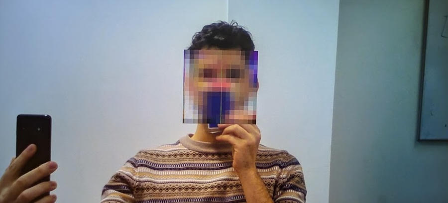
This is what the clown censoring looked like. I had it configured to track a blue color, so I was holding up a blue paper on my nose. It was very fun to play with!
Game plan
HDMI sweeps the image on the screen in rows: left to right, and top to bottom. So when displaying a pixel, I don't know what color the pixel to the right will be. So to apply a filter on an image, I needed to use some previous frame as input. This meant I needed to store the entire region in memory.
My first game plan was as follows:
- In one frame, store the face's image.
- On the next frame, display the previous frame's filtered image in the new detection zone.
Downsampling
The first issue I ran into was storing the detected zone in registers. I had access to the pixel colors in RGB888 format, which is 3 bytes per pixel. So I needed $256 \times 256 \times 24 = 1572864$ flip-flops. That was way too much for the simple Zybo Z7-20 FPGA dev-board I was using.
I decided to downsample the input by a factor of 16; from 256x256 to 16x16. This inherently added some pixelization to the filter, which was fine.
For this crude application, I didn't do any anti-aliasing before downsampling.
I used a 3x3 kernel to apply the filter:
$$ O(x, y) = \sum_{i=-1}^{1} \sum_{j=-1}^{1} I(x+i, y+j) \times K(i, j) $$
The beautiful thing about FPGA is that all these operations can easily be in parallel.
Timing
The second issue was timing. The convolution calculations are hefty, and I needed this done in only a couple clock cycles. This caused timing issues, and I struggled with the screen going black. This is what my code somewhat looked like at this stage:
architecture behavioral of conv3x3 is

    -- 3x3 kernel as float constants
    constant K00 : float32 := to_float(1.0/16.0, float32'high);
    constant K01 : float32 := to_float(2.0/16.0, float32'high);
    constant K02 : float32 := to_float(1.0/16.0, float32'high);
    constant K10 : float32 := to_float(2.0/16.0, float32'high);
    constant K11 : float32 := to_float(4.0/16.0, float32'high);
    constant K12 : float32 := to_float(2.0/16.0, float32'high);
    constant K20 : float32 := to_float(1.0/16.0, float32'high);
    constant K21 : float32 := to_float(2.0/16.0, float32'high);
    constant K22 : float32 := to_float(1.0/16.0, float32'high);

    signal sum : float32;

begin
    process(all)
    begin
        sum := (p00*K00) + (p01*K01) + (p02*K02) +
               (p10*K10) + (p11*K11) + (p12*K12) +
               (p20*K20) + (p21*K21) + (p22*K22);
        result_out <= sum;
    end process;

end architecture;
There were two issues here:
- I wasn't pipelining my operations
- I was using floating point arithmetic
I added a 5 stage pipeline that helped divide the operations into smaller more manageable chunks. Now I could assure the whole calculation would only take 5 clock cycles.
type FSM_STATE is (IDLE, MULT, ADD_1, ADD_2, ADD_3, OUTPUT);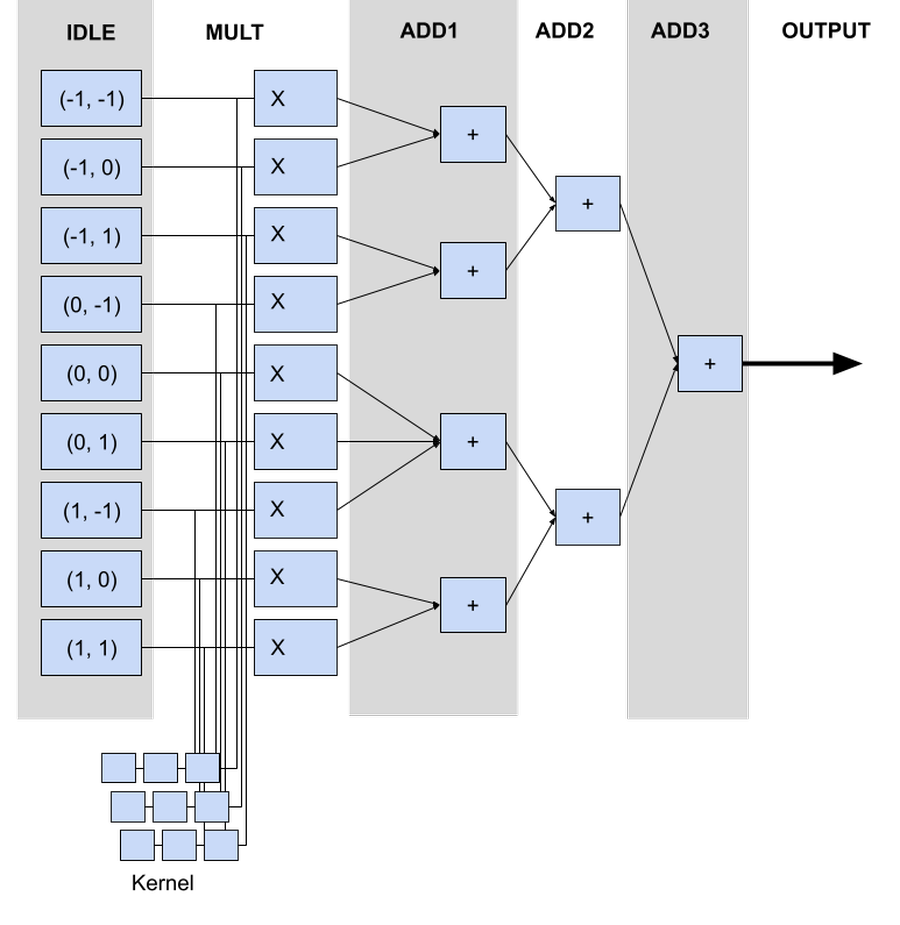
Second, I used integers instead of floats in the calculations. Using integers, I could simply multiply by 1, 2, and 4, and on the output step simply divide by 16 using a right-bit-shift. Using integers allowed me to go much faster, and I saw a noticeable drop in the instability of the design.
In the end, we had an architecture that looked something like this:
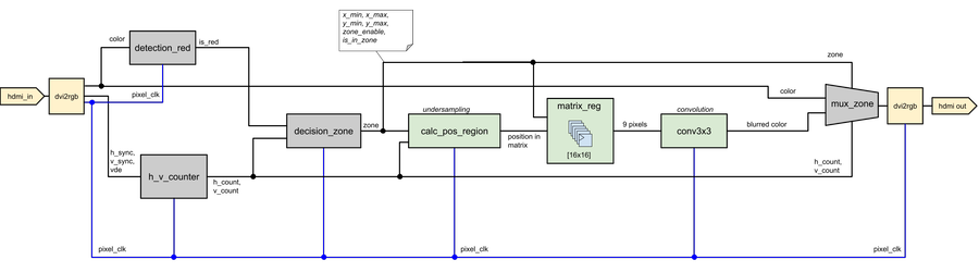
Ultimately, this was a very fun project. Convolutions are everywhere, and opitimizing the calculation for a real-world application is pretty cool. The biggest mistake I made was ignoring BRAM. If I had used BRAM to store the input image, I could have avoided downsampling and taken advantage of the >600 KB of available memory on the Zybo Z7-20 FPGA dev-board.